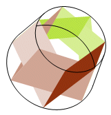
After the release of version 5 of the Geometer's Sketchpad, I made quite a few changes to Perspective Tools and Solid Tools. This is partly because some of the v4 tools were not working out well in v5, and partly because of some new features available in v5. Below is a summary of the changes

The image above illustrates the principle reason for revising the Solid Tools collection. On the left is a frustum constructed in version 4. In the center is the same sketch as it appears in version 5. The natural reaction is to try increasing the depth. In the image at right, the depth has been increased from 100 to 300. The result is even worse, owing to the moiré effect.
The curved surfaces on the iterated solids are not actually curved at all. They are polygons. As the depth is increased, they approach a curve. In v5, the polygons are rendered in a slightly different way. The idea probably is to soften the boundaries. The result is that adjacent polygons have a very fine gap at their common border.
 To see how the solution works, look at this hollow conic frustum of depth seven. The lateral faces are now twice as broad, but no less dense. This causes them to overlap and cover the gaps. The bases have changed too. A base used to be made of isosceles triangles arranged radially, sharing a vertex at the base center. Now the triangle bases overlap and each has its own vertex on the opposite side. This prevents the starburst effect at the center of the frustum base.
I miss the utility value of the previous frustum tool. When the depth had a low setting, the figure was a polyhedral frustum and could assume the form of a right pyramid or prism. By increasing the depth, it became a conic frustum, cone, or cylinder. The new conic frustum does not look like much of anything until the depth is run up, so the polyhedral version has to come from a separate tool.
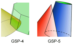
 While looking for a solution, I did some experimenting with overlapping colors. V4 used to suffer from some unpredictable color interference effects, but that does not seem to be a problem with v5. When two overlapping polygons both have 100% opacity, one will cover the other completely, and the dominant surface can be controlled to a limited extent. Here it can be seen that the v4 image blends the colors, while in the v5 image, the red of the cone completely covers the blue of the frustum. This property is what made the hollow surface tools possible. The exterior polygons are placed in front of the interior, preventing the interior from showing through.
The color overlap worked well on the hollow surfaces because they are all curved surfaces. The only edges are where the bases meet the lateral surface. Those edges are loci, not iterations, and they were constructed separately (with far greater difficulty). For a hollow polyhedron, the edges would become a problem because a line segment shows through a polygon interior no matter what the opacity, and the Send To Front (or Back) option applies only to interiors. This is where I got some technical advice from Key Curriculum Press. (Thanks, Scott.) The Properties window for a polygon has an option which I had not noticed before. When the Polygon Frame box is checked, it places a boundary around the polygon. Since it is the same color as the polygon, it is not noticeable at 100% opacity, but when the opacity is lowered, the interior color is lightened while the frame is not.

Although the frame appears to be made of line segments, it is part of the polygon interior, so it can be sent to the back and completely covered by an opaque polygon. The tools in the 2-face family place two conditional polygons on a face. Each of them vanishes when it is turned away from the observer. The exterior face is 100% opaque. The interior face is 20% opaque and has a frame. The exterior face is on the convex side, so it can have conditional line segment edges because there will never be a face covering it. An interior edge may be covered by an exterior face, so a polygon frame is used for interior edges.
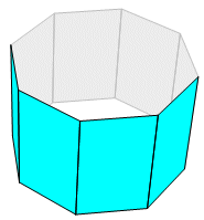
 Here is a hollow prism, the surface of which is constructed with the tool 4-gon 2-Face. The default colors are cyan on the exterior and gray on the interior. The colors can be changed after a face is constructed. Parametric coloring is also possible. In that case, every face plane must be defined separately.
This does not make it possible to construct non-convex solids, e.g., a torus. An image like that would require some of the exterior faces to overlap each other, with no way of identifying which face should be on top. However, it is now possible to show interiors of convex solids, and that is something new. The polygon frame is not carried on iterated images, so any hollow polyhedra will have to be constructed one face at a time.
There are several other tools that have been removed from Perspective Tools and Solid Tools. They include the shade tools, the traced solids and the opaque solids. Since I was getting no use out of them myself, I thought it unlikely that anyone else was using them. The tool files and their documentation were getting cluttered, so I removed these.
Back to Perspective Tools Manual
Back to Whistler Alley Mathematics